
10cas
Dual 0-10VDC to Casambi 2-Channel Dimmer

10cas is a Bluetooth controllable, Casambi enabled, two channel analog 0-10VDC input dimmer that allows connection to a standard 0-10VDC analog dimming master controller to a Casambi network. While the Casambi manufactured CBU-A2D is intended to connect to analog controlled fixtures, the 10cas is the “other side”, allowing for standard 0-10VDC controllers to be utilized with Casambi networks. The 10cas is con nected between a 12-24 VDC Class 2 power supply, and a 0-10VDC master with one or two channels. In addition a single digital, dry contact is supported.
10cas can implement up to three Casambi pushbutton devices, making it an ideal partner for tuna ble white (TW) applications. Multiple 10cas devices can be used in the same network to control different fixtures, channels or zones since the two channels of control can be mapped using the Casambi mobile application. Two channels are 0-100% dimming capable, with a single digital ON/OFF from Dig3.
10cas can be configured with the Casambi app which can be downloaded free of charge from Apple App Store and Google Play Store. Different Casambi enabled products can be used from a simple single luminaire direct control to a complete and full featured light control system where many units automatically form an intelligent mesh network.
INPUT
Voltage range: 12-24 VDC, Class 2
No-load input current: 30 mA
0-l0VDC Input (A and B)
2-wire analog 0-10VDC, two channels
1mA source current, input must sink for control
Top and bottom “trim” and hysteresis user programmable
Digital Input 3
Open connection to Dig3 is considered OFF to Casambi, short Dig3 to RETURN to create an ON state. This input should not be powered, and only used as a dry contact between the two connections.
RADIO TRANSCEIVER
Casambi CBM003B Radio Module
Operating frequencies: 2.401-2.483 Ghz
Maximum output power: typ. +8 dBm
-103 dBm RX sensitivity in long-range mode
CONNECTORS
Wire range, solid & stranded: 0.5 – 1.5 mm2
14 – 22 AWG
OPERATING CONDITIONS
Ambient temperature, ta: -13…+113°F (-25…+45°C)
Max. case temperature, tc: +167°F (+75°C)
Storage temperature: -13…+167°F (-25…+75°C)
Max. relative humidity: 0…80%, non-cond.
![]()
INSTALLATION DETAILS
Connect a Class 2 power supply with l2-24 VDC output voltage to the input connector of l0cas. Make sure not to use a constant current LED driver and make sure that the cable polarity is correct. The product has two 0-l0VDC analog positive input connections, plus one common (RETURN} ground. Connect the 0-l0VDC load wires to a 0-l0VDC master of your choice to give you 0-l0VDC control of your Casambi lighting network.
l0cas can be mapped just like pushbuttons are mapped in the Casambi application. Once you add the l0cas to your Casambi network, navigate to the “More” button at the bottom of the app. Then press “Switches, where the l0cas will be seen. Press on the l0cas that you want to configure, and select each of the two pushbutton items in turn. Then configure each of the two pushbuttons to control a Casambi element by pressing on “Not in Use” .and then select what the pushbutton is to control, most likely “Controls and Element”, which then you can select a certain element to control. Note at the bottom of this screen there are six user-programmable parameters—High and Low Trim, and Hysteresis for each channel. These allow fine-tuning of the bottom and top analog voltage in, and hysteresis allows for managing inputs that may be noisy. Be sure to press “Done” at the top right to save the configuration.
l0cas should not be placed in a metal enclosure, such as metal junction boxes. Metal will attenuate radio signals which are crucial to the operation of the product. If the product will have to install into a junction box, make sure to use a plastic junction box. l0cas is an ETL Listed Open-Type device which means that it will have to be used together with a Class 2 power supply with a maximum output power of l00 VA. The product can be installed outside of the junction box. Make sure to comply with National Electric Code in installation and when selecting installation wires.
TYPICAL CONNECTION DIAGRAM
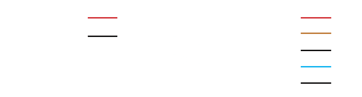
* The relay must be protected against inductive over voltage spikes, i.e. it must have a flyback diode. Do not connect a typical PCB relay without the diode.
Dimensions are in mm. * Tc point is on bottom side. 2.2 x 1.2 x 0.7 Inches | 72.6 x 30.0 x 18.0 mm | 0.8 oz ( 23 g )
RANGE DETAILS
The range between two DMXcas or between a DMXcas and a smartphone can vary depending on obstacles and surrounding material. In open-air, the range between two DMXcas’ can be in excess of 200 ft, but if the unit is encapsulated into a metal structure, the range can be only a few feet. Therefore, thorough testing is highly suggested.
Casambi uses mesh network technology so each DMXcas acts also as a repeater. When testing the network, it is important to test that each unit can be controlled from any point of the network covered area.
COMPLIANCE STATEMENT
This device complies with part 15 of the FCC Rules. Operation is subject to the following two conditions:
(1) This device may not cause harmful interference, and
(2) This device must accept any interference received, including interference that may cause undesired operation.
Warning
Changes or modifications not expressly approved by DMX Engineering and Design LLC could void the user’s authority to operate the equipment.
FCC Interference Statement
This equipment has been tested and found to comply with the limits for a Class B digital device, pursuant to Part 15 of the FCC Rules. These limits are designed to provide reasonable protection against harmful interference in a residential installation. This equipment generates, uses and can radiate radio frequency energy and, if not installed and used in accordance with the instructions, may cause harmful interference to radio communications. However, there is no guarantee that interference will not occur in a particular installation. If this equipment does cause harmful interference to radio or television reception, which can be determined by turning the equipment off and on, the user is encouraged to try to correct the interference by one of the following measures:
Reorient or relocate the receiving antenna.
Increase the separation between the equipment and receiver.
Connect the equipment into an outlet on a circuit different from that to which the receiver is connected.
Consult the dealer or an experienced radio/TV technician for help.
Radiation Exposure Statement for Canada
This device complies with Industry Canada’s license-exempt RSSs. Operation is subject to the following two conditions:
(1) This device may not cause interference
(2) This device must accept any interference, including interference that may cause undesired operation of the device. This equipment is exempt from the routine RF exposure evaluation requirements of RSS-102. This equipment should be installed and operated with a minimum distance of 20 cm between the antenna and the user or bystanders.
Le présent appareil est conforme aux CNR d’Industrie Canada applicables aux appareils radio exempts de licence. L’exploitation est autorisée aux deux conditions sui-vantes:
(1) l’appareil ne doit pas produire de brouillage;
(2) l’utilisateur de l’appareil doit accepter tout brouillage radioélectrique subi, même si le brouillage est susceptible d’en compromettre le fonctionnement. Ce matériel n’est pas sujet à l’évaluation habituelle d’exposition RF selon RSS102. Ce matériel devrait être installé et exploité en gardant une distance minimale de 20


