
Sets the actual high endpoint independently for In A and In B. Released default is 100.
0-10 V INPUT → CASAMBI · TWO INDEPENDENT ELEMENTS
10cas
Keep the analog controller. Make its two channels part of Casambi.
10cas measures two externally generated 0-10 V signals and publishes two independent Casambi Element levels. Trim each field source to its real endpoints, reject noise with per-channel hysteresis, and let legacy analog controls participate in the mesh.
 MADE IN USADesigned, built and supported in Mesa, Arizona
0-10 V CONTROLLER → 10cas → CASAMBI ELEMENTS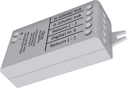
ANALOG INCASAMBI
Two measured voltages become two independent 8-bit Element levels. This is an input interface—it does not source 0-10 V.
2 inputsindependent 0-10 V channels
0-255published Element level per channel
32 samplesaveraged before trim and hysteresis
DIRECTION MATTERS
Measure analog.
Publish to the mesh.
Use 10cas when the existing controller already generates the voltage. Input A maps to Element 1 and Input B maps to Element 2; both can then be assigned to Casambi scenes, groups, automations or control logic.
Existing controllerTwo return-referenced 0-10 V outputs
→
10casAverage + trim + hysteresis + 8-bit mapping
→
Casambi networkElement 1 and Element 2 mapped independently
INTERACTIVE 0-10 V MAPPER
See exactly what each input publishes.
Move either source and adjust its commissioned bottom and top endpoints. The example shows the resulting Casambi level; it does not configure hardware.
Apply field voltages
Each channel is independent. Trim only enough to match the actual source range.
INPUTS, NOT OUTPUTS
The field controller must provide the voltage. Do not connect these terminals as though 10cas were a 0-10 V source.
The field controller must provide the voltage. Do not connect these terminals as though 10cas were a 0-10 V source.
Two independent Element values
CHANNEL RELATIONSHIPIndependent
UPDATE FILTERPer-channel hysteresis
SEVEN ANALOG PARAMETERS
Commission the real sources—not an idealized 0 and 10 volts.
Top and bottom trim establish each usable voltage window. Hysteresis prevents stable input noise from generating repeated Casambi updates. The alternate curve is global.
Sets the actual low endpoint independently. Released default is 0.
Defines the minimum change before that Element republishes. Default is 3 plus the firmware offset.
Optional alternate analog transfer curve. Leave Off for normal commissioning unless the project explicitly requires it.
Each analog input is averaged before trim, hysteresis and the final 0-255 mapping are applied.
Prove 0 V, midpoint and 10 V on each source. Do not assume two controllers have identical endpoints or noise.
FIVE ACTIVE TERMINALS
Power, two signals and one shared reference.
Install as an indoor Class 2 low-voltage interface and keep the radio end clear of grounded metal and dense power wiring.
POWER + / POWER -
12-24 VDC Class 2 supply, polarity sensitive. Do not use a constant-current LED output.
IN A / IN B
Positive voltage from the two external 0-10 V sources. Input A maps to Element 1; Input B maps to Element 2.
RETURN
Common analog reference for both sources. Verify the sources are compatible with a shared return.
Current released guidance: RELAY and SENSOR are reserved and not supported at this time. Leave both unconnected. Route analog conductors away from contactors, switching power and line voltage.
MEASURE · MAP · PROVE
Turn over the actual analog endpoints.
Record both Element assignments, trim values, hysteresis, curve selection and measured 0 V / midpoint / 10 V results.
PDFInstallation manualRatings, terminals and installation.PDFCommissioning guideElements, parameters and acceptance tests.
Have an unusual analog source?
Bring us its output specification and reference scheme.
Bring us the problem ↗