

CASAMBI ENABLED · DUAL 0–10 V MASTER

casTen

Two clean DC control channels. Calibrated for the equipment at the other end.

casTen provides two independently commanded 0–10 V outputs with strong source/sink drive and per-channel top and bottom trim. Use them as separate controls or a coordinated warm/cool pair, then configure both digital terminals for the switches and equipment contacts the project needs.

United States flagMADE IN USADesigned, built and supported in Mesa, Arizona
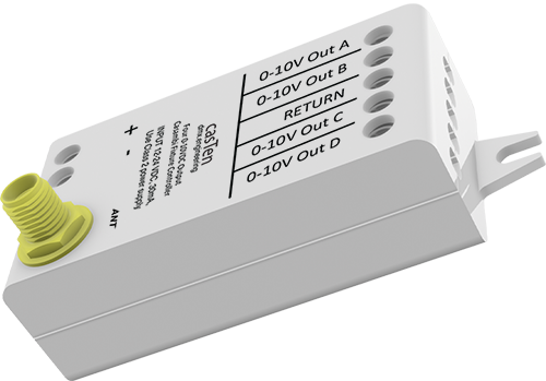
CASAMBI → casTen → TWO 0–10 V CONTROL INPUTScasTen two-channel 0–10 V controller
OUT AOUT B

Independent analog control with a common reference, individual trims and two universal Digital I/O points.

2 × 0–10 Vindependent source/sink outputs
20 mA/channelpublished source and sink capability
12 parametersfour analog + eight Digital I/O

ANALOG CONTROL THAT MEETS THE LOAD WHERE IT IS

Drive it cleanly.
Trim it deliberately.

Each channel uses a 16-bit internal PWM engine filtered into a clean DC control voltage, with the output scaled between that channel’s commissioned bottom and top limits.

INDEPENDENT CHANNELS

A and B stand on their own

Casambi channels 1 and 2 independently command Out A and Out B. Control separate zones, separate functions or a coordinated two-channel load.

TOP + BOTTOM TRIM

Set the usable window

Raise the bottom only when the equipment needs a reliable minimum. Lower the top only when its useful maximum is below 10 V.

MEASURE AT THE LOAD

Calibrate the real circuit

Wire length, common impedance and the controlled device can change the voltage it actually sees. Measure at the equipment terminals.

INTERACTIVE 0–10 V CALIBRATION LAB

Move the command.
See the trimmed voltage.

Select a channel and set its Casambi level, bottom trim and top trim. The simulated meter shows the resulting clean DC control voltage at the load.

Configure Channel A

Keep bottom below top. Defaults are 0% bottom and 100% top.

0–10 V OUT A · AT LOAD5.00 V
0.0–10.0 V commissioned window
0–10 V OUT B · AT LOAD5.00 V
0.0–10.0 V commissioned window

Channel A: 50% command scaled through 0–100% trim produces 5.00 V.

01Start at defaults

Bottom 0%, top 100%. Establish the untrimmed behavior first.

02Measure minimum

Command 0% and raise bottom only if the load needs a higher reliable floor.

03Measure maximum

Command 100% and lower top only when the equipment requires it.

04Prove the curve

Measure 25%, 50% and 75%, then test scenes and fades.

THE TWO ANALOG CHANNELS ALWAYS REMAIN

Choose the Digital I/O
arrangement around them.

The Casambi profile controls whether each digital terminal appears as a PushButton input or output Toggle. Its Direction parameter must match the selected profile.

PROFILE 45166

In1 · In2

Two independent PushButtons, each mapped to its own Casambi Element. Both Direction parameters must be Input.

PROFILE 46652

In1 · Out2

One mapped PushButton and one output Toggle. Direction must be Input for I/O 1 and Output for I/O 2.

PROFILE 46653

Out1 · Out2

Two output Toggle controls. Both Direction parameters must be Output.

TWO UNIVERSAL DIGITAL TERMINALS

Configure each point
for the field device.

Inputs accept only a passive closure to Ground. Outputs are low-side electronic contacts for compatible low-voltage sensing circuits—not powered loads.

FIELD DEVICESwitch, button, sensor or contact-sense input
→
I/O 1 + I/O 2 + GROUNDcasTen
→
CASAMBI FUNCTIONMapped PushButton or output Toggle
DIGITAL I/O 1Casambi channel 3 when output

Ready · passive contact open

DIGITAL I/O 2Casambi channel 4 when output

Ready · passive contact open

STATIC / PULSEDMatch the switch

Follow a maintained contact or toggle from each momentary closing edge.

HOLD / DOUBLE-TAPDim from one contact

Choose fixed or alternating direction and optional endpoint commands.

GANG 1–10Synchronize stations

Share level and next dim direction with compatible NED controls.

NORMAL / INVERTEDDefine output ON

Choose whether Casambi ON closes or releases the electronic contact.

MULTISWITCH GANG 1–10

The 0–10 V job and the switch jobs
can be completely independent.

Each casTen input can join its own Gang and map to any Casambi Element. The inputs can assist the fixtures driven by Out A/Out B—or control other rooms, scenes and Elements elsewhere on the network.

casTen I/O 1GANG 2Lobby scene control
⇄
CASAMBI MESHSHARED MEMORYAbsolute level + next direction
⇄
casTen I/O 2GANG 7Conference-room control

TWELVE VENDOR PARAMETERS

Four tune the analog path.
Eight define the field I/O.

Parameter order is part of the firmware interface. Keep the profile and per-terminal Direction settings together during commissioning and closeout.

IDParameterWhat it controls
0Top Trim Ch 1

Effective 25–100% upper endpoint for Out A

1Bottom Trim Ch 1

Lower endpoint for Out A

2Top Trim Ch 2

Effective 25–100% upper endpoint for Out B

3Bottom Trim Ch 2

Lower endpoint for Out B

4–7I/O 1 Direction · Action · Mode · Polarity

Input/output role plus independent input and output behavior

8–11I/O 2 Direction · Action · Mode · Polarity

Matching four-parameter set for the second terminal

Firmware does not prevent crossed trim values. Keep bottom below top, measure at the controlled equipment, and leave casTen powered for at least three seconds after parameter completion.

COMMON-REFERENCE ANALOG CONTROL

Two outputs.
One signal common.

Power casTen from a polarity-correct 12–24 VDC Class 2 source. Connect Out A, Out B and Ground according to the controlled equipment manufacturer’s 0–10 V wiring diagram.

12–24 VDC
Class 2 supply
→
casTen0–10 V OUT A0–10 V OUT BGROUND + I/O 1 + I/O 2
TWO-CHANNEL 0–10 V EQUIPMENTIndependent loads or warm/cool pair

Installation essentials

Supply
12–24 VDC Class 2
Analog outputs
Two independent 0–10 V channels
Drive
20 mA source and sink per channel, published
Reference
Common Ground for analog and digital points
Environment
Indoor, IP20/open-type

Do not connect the analog outputs to mains, DALI, constant-current LED outputs or a powered control signal. Never apply external voltage to either Digital I/O terminal.

PLAN · CALIBRATE · COMMISSION

Take every voltage
and I/O decision to the job.

Use the installation guide for ratings and wiring, then the commissioning guide for trim calibration, profiles, all twelve parameters and acceptance testing.

Need to match unusual 0–10 V equipment?

Bring us its input impedance, minimum/maximum voltage, wiring distance and channel relationship.

Bring us the problem ↗