

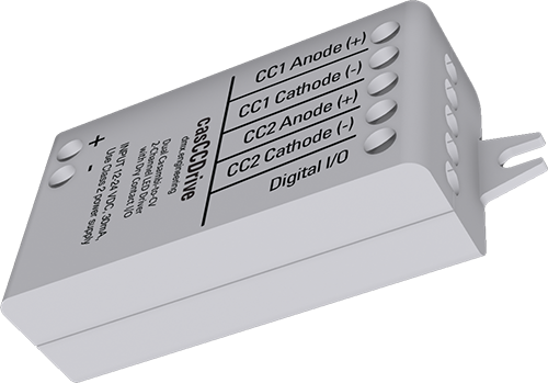
CASAMBI ENABLED · DUAL CONSTANT-CURRENT DRIVER

casCCDrive

Two LED channels.
One compact driver.
More ways to use them.

Drive two independent constant-current LED loads—or pair warm and cool channels for tunable white. Then use the profile-selected Digital I/O to bring a switch into Casambi or signal compatible equipment.

United States flagMADE IN USADesigned, built and supported in Mesa, Arizona
CASAMBI → casCCDrive → CONSTANT-CURRENT LEDScasCCDrive dual-channel constant-current LED driver
CH 1CH 2

Independent outputs or one tunable-white pair.

2 channelsindependent constant-current outputs
25–700 mAper channel in 25 mA steps
1 Digital I/Oprofile-selected input or output

ONE DRIVER · TWO DISTINCT JOBS

Use the channels separately.
Or blend them together.

The selected Casambi profile determines how the two physical current outputs appear to the user.

MODE 01

Two independent outputs

Channel 1 and Channel 2 become separate dimmable loads. Give each LED string its own current setting, first-light adjustment, wiring and Casambi control.

casCCDriveCH 1LED LOAD ACH 2LED LOAD B
  • Two separate luminaires or LED engines
  • Independent 0–100% dimming
  • Independent 25–700 mA current ceilings
MODE 02

Tunable white

Connect one output to the warm LED channel and the other to the cool LED channel. Casambi then blends their levels to move across the luminaire’s available CCT range.

casCCDriveWARM2700KCOOL6500K
  • One intensity control for the luminaire
  • One warm-to-cool CCT control
  • Actual CCT range comes from the connected LED module

INTERACTIVE CHANNEL STUDIO

See what the two outputs do.

Switch between independent and tunable-white operation. This browser demonstration illustrates channel behavior; it does not configure hardware.

CHANNEL 1
70%100 mA ceiling
CHANNEL 2
35%100 mA ceiling

Independent mode: each Casambi control drives its own LED load.

ONE TERMINAL · TWO POSSIBLE ROLES

The Digital I/O is part
of the control story.

The selected Casambi profile exposes X2-5 as either a dry-contact input or a low-side electronic output. The role is selected by profile—not by a vendor parameter.

FIELD DEVICEDesigner button or passive contact
→
X2-5 + GROUNDcasCCDrive
→
CASAMBI RESULTPushButton Element command

Ready · passive contact open

FOLLOWMaintained contact

Closed and open states follow the physical switch, with normal or inverted polarity.

TOGGLEMomentary button

Each press changes the mapped Casambi state without requiring a maintained switch.

HOLD / DOUBLE-TAPMore from one button

Choose fixed or alternating dim direction and profile-supported double-tap behavior.

GANG 1–10Multi-location memory

Keep compatible NED wall stations aligned on logical level and next dim direction.

MULTISWITCH GANG 1–10

One press at any station.
No catch-up press.

Assign the casCCDrive input and other compatible NED inputs to the same Gang. They exchange the last level and next dim direction so every station starts from the same remembered state.

STATION AcasCCDrive inputButton changes shared level
⇄
CASAMBI MESHGANG 3Level + direction memory
⇄
STATION BCompatible NED inputNext press acts immediately

SEVEN VENDOR PARAMETERS

Set the hardware limits.
Then shape the behavior.

Both current ceilings and low-end first-light behavior are independently configurable. The Digital I/O receives the same input action and mode vocabulary used across compatible DMX Engineering products.

IDParameterWhat it controls
0Channel 1 Current

25–700 mA in 25 mA increments

1Channel 2 Current

25–700 mA in 25 mA increments

2Channel 1 First-Turn-On

Low-end PWM floor for reliable first light

3Channel 2 First-Turn-On

Independent low-end PWM floor

4Digital Input Action

Normal, inverted or MultiSwitch Gang 1–10

5Digital Input Mode

Follow, toggle, hold-dim or double-tap behavior

6Digital Output Polarity

Normal or inverted logical contact state

After changing vendor parameters, keep casCCDrive powered for at least three seconds before cycling power so the deferred nonvolatile write can complete.

WIRE EACH CURRENT PATH INDEPENDENTLY

Two outputs.
No shared LED return.

Use a 12–48 VDC Class 2 constant-voltage supply. Maintain at least 2 V of headroom above the highest LED-string forward voltage.

12–48 VDC
Class 2 constant-voltage supply
→
casCCDriveCH 1 + / −CH 2 + / −X2-5 DIGITAL I/O
LED LOAD 1Dedicated anode + cathode
LED LOAD 2Dedicated anode + cathode

Installation essentials

Supply
12–48 VDC Class 2, constant voltage
LED outputs
Two independent constant-current paths
Current
25–700 mA per channel
Headroom
Supply at least 2 V above LED-string Vf
Environment
Indoor, open-type device
Radio
Keep outside metal enclosures

Do not tie channel anodes or cathodes together, share a return conductor, ground an LED cathode, or feed the product from another constant-current driver.

PLAN · INSTALL · COMMISSION

Take the details
to the project.

Use the installation sheet for ratings and connections, then the commissioning guide for profiles, vendor parameters, Digital I/O and acceptance testing.

Building a constant-current fixture?

Bring us the LED current, forward voltage, channel plan and desired control experience.

Talk to DMX Engineering ↗